Cell Fenders

Features

DockGuard Cell Fenders have a cylindrical construction, designed specifically to allow for uniform compression and for applications subject to circular /axial motion. They are produced in a number of differing compounds – depending upon the characteristics needed to meet each requirement – but always using marine quality compounds which are highly resistant to the effects of ozone degradation, UV radiation and water borne oil pollution.

Cell Fenders have a normal energy to reaction capability. The normal compression is 52.5% and the maximum compression is 55%. They are available in a standard range of popular sizes from 300mm to 2500mm.

Key Benefits

DockGuard’s Cell Fenders have a well established reputation for durability and performance. They are highly effective in angular berthing applications, and their large footprint ensures good force distribution and excellent shear force resistance. They are also easy to install and require very little maintenance.

Applications

Cell fenders are ideally suited to applications that are subject to circular motion and extreme weather conditions or where heavy and angular berthing may be required. With a higher reaction than cones and leg fenders, cell fenders are generally used on quay structures rather than dolphin berths. They are suitable for a wide range of berthing applications – including oil and LNG facilities, offshore platforms, bulk terminals, container berths, RoRo and cruise terminals – and are therefore an obvious choice for multi-use berths.

Cell Fender Specifications

<< swipe table content >>

Energy ReactionHØAØCBoltsEWeight Kgs
DCE4004005506504 x M242575
DCE5005005506504 X M242595
DCE6306307008404 X M3025220
DCE80080090010506 x M3030400
DCE10001000110013006 x M3635790
DCE11501150130015006 x M42401200
DCE12501250145016506 x M42401500
DCE14501450165018506 x M48422300
DCE16001600180020008 x M48453000
DCE17001700190021008 x M56503700
DCE20002000200022008 x M64505000
DCE225022502300255010 x M64577400
DCE250025002700295010 x M647010700

All dimensions in mm. All weights in Kgs per 1000mm length.

Cell Fender Performance

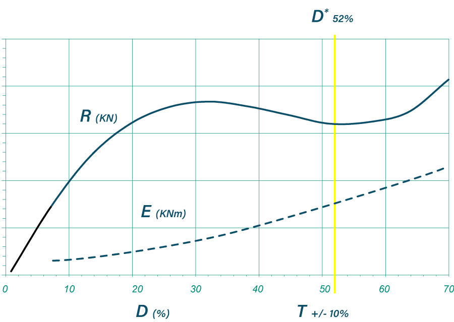
Cell Fender Energy and Reaction Graph

D*= Rated Deflection
R = Reaction KN
E = Energy KNm
D = Deflection %
T = Tolerance +/- 10%

<< swipe table content >>

Energy
Reaction
DCE
400
DCE
500
DCE
630
DCE
800
DCE
1000
DCE
1150
DCE
1250
DCE
1450
DCE
1600
DCE
1700
DCE
2000
DCE
2250
DCE
2500
D1.0E9183874153233300467629754122720622829
R55871372113494625457348941009139720852574
D1.1E10194079162246316493664796129621632968
R59921442233684885757759441065147421882701
D1.2E11204283171259333520699838136522653108
R62971522363885136068169931122155122912828
D1.3E11214588179272350546734880143323673247
R6510216024940753963685710431178162923942956
D1.4E12234792188285367572769923150224693387
R6810716826242756566789810931235170624983083
D1.5E12244997197298384598804965157025713526
R7111217527444659169793911431291178326013211
D1.6E1325511012053114016258391007163926733666
R7511718328746661772898011931348186127043338
D1.7E1426531062143244186518741049170827753805
R78122191300485643758102212431404193828073466
D1.8E1427551102233374356779091091177628773945
R81127199313505669789106312931461201529113593
D1.9E1528571152313514527039441134184529794084
R84132206325525695820110413431517209330143721
D2.0E1529601192403644697309791176191430814224
R88137214338544721850114513931574217031173848
D2.1E16306212424937748575610141218198231824363
R91142222351564747881118614431630224732203976
D2.2E17316412825739050278210491260205132844503
R94147230364583773911122714931687232533244103
D2.3E17326613326640351980910841302211933864642
R97152237376603799942126915431743240234274230
D2.4E18336813727541653683511191344218834884782
R100157245389622825972131015931800247935304358
D2.5E18357014228342955386111541387225735904921
R1041622534026428511003135116431856255736334485
D2.6E19367314629244257088711891429232536925061
R1071672614156618771033139216931913263437374613
D2.7E20377515130145558791412241471239437945200
R1101722684276819031064143317431969271238404740
D2.8E20387715630946860494012591513246238965340
R1131772764407009291094147417932026278939434868
D2.9E21397916031848162196612941555253139985479
R1161822844537209551125151518432082286640464995
D3E21408116532749563899313291598260041005619
R1201872924667409811156155718932139294441505123
D4E224489180357545700109014631752285345106182
R13120532151381310781276171320822350324045635633

Cell Fender Support Weight

The tables below give an indication on whether support chains are required for use on the fender system

DGCCell Fender mounted Horizontally
D1Max support = 1.12 x n x w
D2Max support = 1.41 x n x w
D3Max support = 1.82 x n x w
DGCCell Fender mounted Vertically
D1Max support = 1.31 x n x w
D2Max support = 1.79x n x w
D3Max support = 2.24 x n x w

n = number of Cell Fenders
w = weight of Cell Fender

Print Friendly, PDF & EmailDownload Datasheet
en_GBEN